Wired System, 5-Wire Network #
The success of the WaveLinx Wired (5-wire) Lighting System relies on the accurate wiring of Belden 1502 / 1502P cable daisy-chained between panels and lighting devices with end devices terminated. DO NOT homerun or T-tap wiring of devices. Each device exhibits the correct layout of the 5 wires in the Belden cable and needs to be followed with accuracy for proper power and communication. UIMs have a different wiring configuration than other devices. Any wiring landed incorrectly will cause issues at project startup and each device will have to be inspected. Use of alternate 5-wire cabling will void all Cooper warranties.
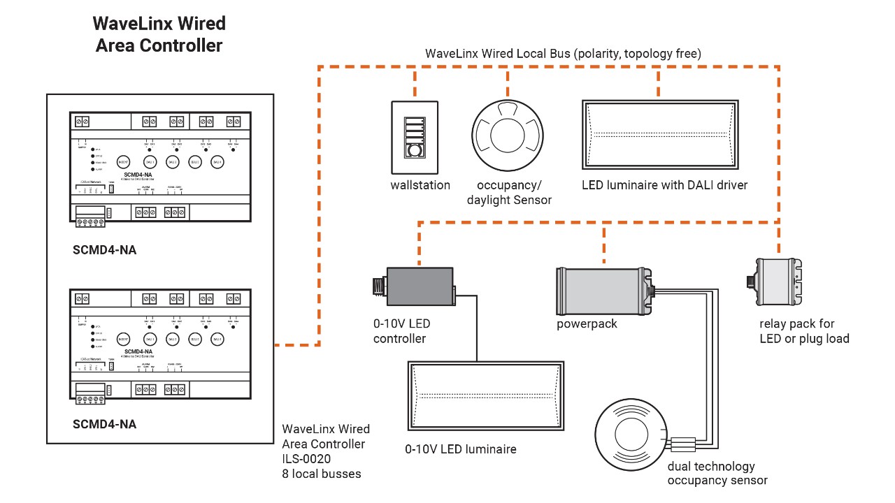
Wired System, 2-Wire DALI Network #
The WaveLinx Wired (2-wire) DALI Lighting System is an open topology network where you can daisy-chain, T-tap, and star wire devices. Use 18-14AWG 2 conductor wire, and each DALI loop / output can be 1000 feet. Wire is polarity free and max 64 devices per loop, 55 or less is preferred.
Communication Wiring #
 Ensure that all high voltage and Class-2 low voltage wiring remains separated by a minimum distance of 1 foot and is installed per NEC code.
Dimming, 0-10v #
Verify all areas that require dimming. Dimmed zones will require 0-10v wiring to run between all fixtures back to the Lighting Control Panel. Test all dimming zones by removing the 0-10v wiring from the panel, fixtures will go full bright, touch the low voltage wires together, fixtures will go full dim. All fixtures should be tested and dimming correctly for each connected zone.
Dimming, ELV-MLV #
The SC-UN Source Controller has ELV-MLV dimming built into the panel, wire loads per the included instructions. Additional dimming modules are required for ILS, ILM, & ILL Lighting Panels when controlling ELV-MLV fixtures. A PD-216, LDCM, or LR01 dimming module will be installed between the panel and the fixture(s) to convert 0-10v dimming to line volt dimming. Wiring diagrams are included with the Controls plans.
Occupancy Sensors #
Install ceiling occupancy sensors 4-6 feet away from air supply vents. Locations of devices shown on plans are just a graphical representation. All wired sensors will need to be configured with correct timeout and sensitivity adjusted and is the responsibility of the Electrical Contractor. DO NOT leave occupancy sensors in factory default Auto mode.
Documentation / Maintenance #
Document all relays, dimming outputs, and additional device inputs being used for controlled zones. For any future maintenance, it is best practice to label field devices for what they are controlling and create an accurate as-built of the route of the 5-wire or 2-wire network, and device locations for future troubleshooting.
Manual testing of relays and dimming outputs from the panel can be done before we arrive for programming. View documentation provided with your panel for instructions.
Replacement devices need to be programmed once installed, schedule a technician to be on-site at the same time to avoid any system interruptions. Power down the system when altering any networked device and the 5-wire network.
